Nov.
17, 2025
Contents
Sheet Metal Bending and Forming Guidelines for Designers
Material Selection & Thickness

You should use Bending Guidelines when you design sheet metal parts. Correct bends help you get the right size and fit. You save material and spend less money. You work faster and do less extra work. Checking quality helps you find mistakes and keep parts working well. Smart design choices make parts work better and help production go smoothly. Always use these guidelines when you start a new project.
You need to pick the right sheet metal for your project. Stainless steel is the most popular choice in factories. It makes up more than 60% of the market in 2025. Steel also has a big part of the market. Aluminum is used in many places. The table below shows how much each material is used:
Material | Market Share (%) | Year |
|---|---|---|
Stainless Steel | Over 60% | 2025 |
Steel | Significant | 2024 |
Aluminum | Not specified | N/A |
Stainless steel is strong and does not rust. Steel costs less and can be used in many ways. Aluminum is light and easy to shape. You find these materials in things like appliances, cars, kitchen tools, and airplane parts.
Tip: Pick a material that fits your part’s job. Think about how strong it needs to be, how heavy it is, and what it will do.
You must choose the right thickness for your design. Thickness changes how you bend and shape the metal. Thin sheets (0.2–1 mm) let you make sharp bends. Thick sheets (over 2 mm) need bigger bends so they do not crack. If your sheet is less than 6 mm thick, make the bend radius the same as the thickness. If your sheet is between 6 mm and 12 mm, use a bend radius 1.5 times the thickness. If your sheet is thicker than 12 mm, use a bend radius about three times the thickness.
Note: Keep the thickness the same everywhere on your part. If the thickness changes, you might have trouble bending and shaping the metal.
You should know how your material acts when you shape it. Stainless steel does not rust and stays strong after bending. Steel bends easily and works for many shapes. Aluminum is soft and lets you make tricky shapes. Each material acts differently when you press or bend it. If you know these things, you can stop cracks, wrinkles, and other problems.
Stainless steel: strong, lasts long, does not rust
Steel: costs less, can be used in many ways, bends easily
Aluminum: light, good for sharp bends
Your design gets better when you match the material and thickness to what your part needs to do.
You need to follow Bending Guidelines to avoid cracks and weak spots in your sheet metal parts. The minimum bend radius is the smallest curve you can make without damaging the metal. Each material has its own minimum bend radius. If you bend the metal too sharply, you might see cracks or lose strength.
The table below shows the recommended minimum bend radius for steel and aluminum at different gauges:
Gauge | Minimum Bend Radius: Steel (inches) | Minimum Bend Radius: Aluminum (inches) |
|---|---|---|
3 | 0.239 | 0.229 |
6 | 0.194 | 0.162 |
10 | 0.135 | 0.102 |
14 | 0.075 | 0.064 |
18 | 0.048 | 0.040 |
22 | 0.030 | 0.025 |
24 | 0.024 | 0.020 |
You can also see how the minimum bend radius changes with gauge in this chart:

Tip: Always check the minimum bend radius for your material before you design a bend. This helps you follow Bending Guidelines and keep your part strong.
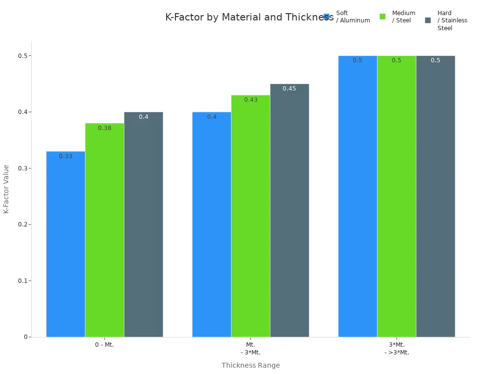
You must understand the K-factor and bend allowance to get the right size and shape for your flat pattern. The K-factor tells you how much the metal stretches when you bend it. It depends on the material and thickness. The bend allowance is the extra length you need to add for the bend.
Here is a table showing typical K-factor values for different materials and thickness ranges:
Material Type | Thickness Range | K-Factor Value |
|---|---|---|
Soft / Aluminum | 0 - Mt. | 0.33 |
Medium / Steel | 0 - Mt. | 0.38 |
Hard / Stainless Steel | 0 - Mt. | 0.40 |
Soft / Aluminum | Mt. - 3*Mt. | 0.40 |
Medium / Steel | Mt. - 3*Mt. | 0.43 |
Hard / Stainless Steel | Mt. - 3*Mt. | 0.45 |
Soft / Aluminum | 3Mt. - >3Mt. | 0.50 |
Medium / Steel | 3Mt. - >3Mt. | 0.50 |
Hard / Stainless Steel | 3Mt. - >3Mt. | 0.50 |
You can see how K-factor values change in this chart:
When you calculate bend allowance, you need to know these parameters:
Parameter | Description |
|---|---|
Bend Angle | The angle the sheet travels from flat to formed shape, calculated as the swept angle. |
Inside Radius | The radius of the bend on the inner side of the metal sheet, affecting material flow and deformation. |
Material Thickness | The thickness of the sheet, which should be measured for accuracy. |
K-Factor | The ratio of the neutral axis location to the material thickness, typically ranging from 0.3 to 0.5, influencing bend allowance calculations. |
Note: Use the right K-factor for your material and thickness. This helps you follow Bending Guidelines and get accurate flat patterns.
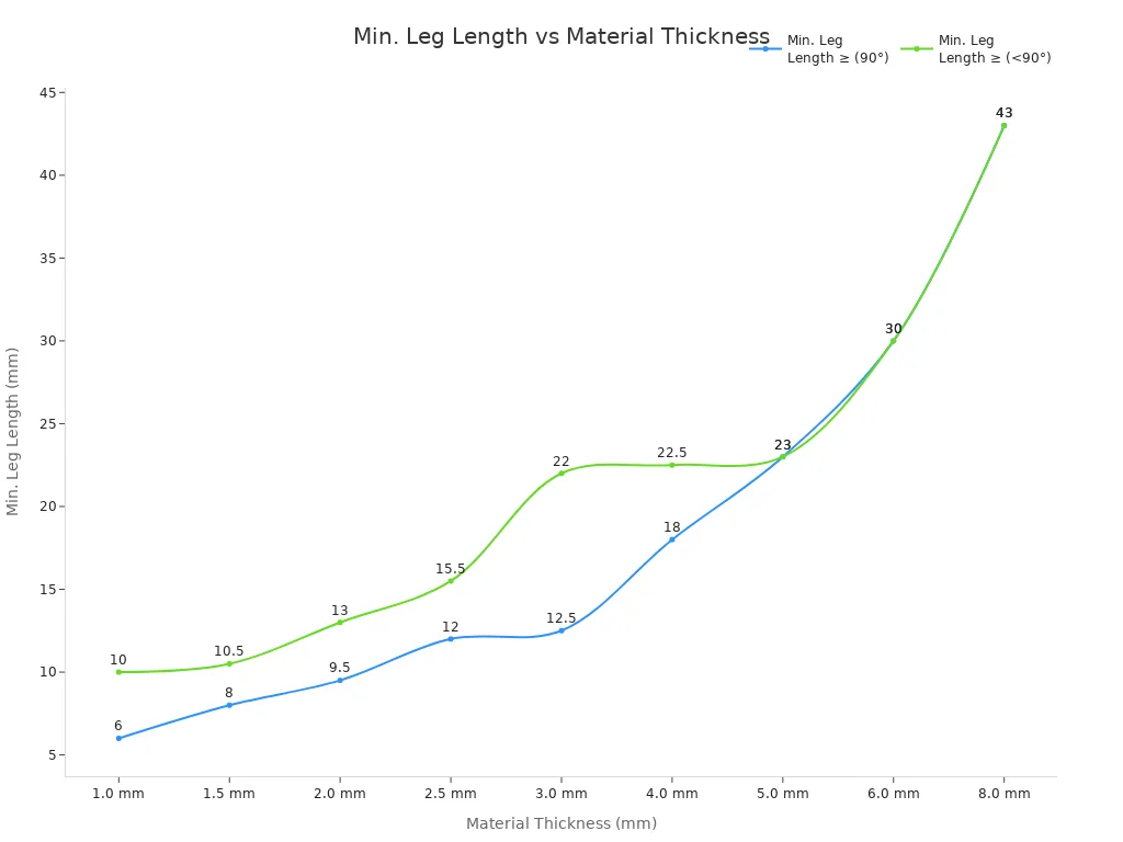
You need to set the right flange length and U-channel proportions to keep your part strong and easy to make. If the flange is too short, the metal can wrinkle or lose shape. If the U-channel is too narrow, tools may not fit, and the part may crack.
The table below shows the minimum leg length for different material thicknesses and bend angles:
Material Thickness (T) | Min. Leg Length ≥ (90°) | Min. Leg Length ≥ (<90°) |
|---|---|---|
1.0 mm | 6 mm | 10 mm |
2.0 mm | 9.5 mm | 13 mm |
3.0 mm | 12.5 mm | 22 mm |
6.0 mm | 30 mm | 30 mm |
8.0 mm | 43 mm | 43 mm |
You can see the relationship in this chart:
Follow these tips for flange and U-channel design:
For air bending, make the flange length at least 4 times the thickness.
For bottoming, increase the flange length to 6 times the thickness.
Keep the internal width of U-channels at least 4 times the thickness.
Make the flange height at least 2 times the thickness.
Use an inner bend radius of at least 1.5 times the thickness to reduce cracking.
Alert: Short flanges may need special tools or extra steps. Avoid placing holes or notches close to short bends.
You must pay attention to the grain direction when you design bends. Grain direction comes from how the metal is rolled. It affects how the metal acts when you bend it.
Bending with the grain makes the bend easier but can cause cracks.
Bending against the grain gives you a stronger bend but can also crack hard metals.
The way you bend changes how stress spreads in the metal.
Grain direction means the metal has different strength in different directions. If you bend parallel to the grain, you stretch the crystals and may see cracks. If you bend across the grain, you spread the stress and get a stronger bend.
Tip: Always check the grain direction before you set your bend lines. This helps you follow Bending Guidelines and avoid weak spots.
Quick Checklist for Bending Guidelines:
Check minimum bend radius for your material and thickness.
Use the right K-factor and bend allowance for flat pattern design.
Set flange length and U-channel proportions to keep parts strong.
Watch grain direction to avoid cracks and weak bends.
Define fold lines clearly and avoid sudden thickness changes near bends.
Plan for springback by testing your design with sample bends.
You improve manufacturability and quality when you follow Bending Guidelines in every step of your design.
You must place holes, slots, and cutouts carefully near bends. If you put them too close, the metal can tear or warp during bending. You protect your part by keeping a safe distance between these features and the bend lines.
Keep holes, slots, or cutouts at least 2.5 times the material thickness away from any bend line.
This spacing helps prevent deformation and keeps your part strong.
If you need to add features close to a bend, test your design with a sample piece first.
Tip: Always measure the distance from the edge of the feature to the bend line, not just the center. This helps you avoid mistakes.
You use notches and bend reliefs to stop tearing and distortion when you bend sheet metal. These small cuts or shapes let the material move and release stress.
Tear-drop relief cuts help release stress slowly, which keeps precision parts intact.
Well-designed relief cuts improve bend quality and stop unwanted tearing.
Bend reliefs create space for the metal to deform, so it does not compress and tear.
When you bend metal, the outside stretches and the inside compresses. Without reliefs, compressed metal can distort.
Reliefs let the material move freely, reducing warping and tearing.
Bend reliefs are small incisions that separate the area to be folded from the rest of the part.
You need reliefs where bends meet flat surfaces to keep the part clean and free from deformation.
Alert: If you skip bend reliefs, you risk cracks and poor-quality bends.
You must follow clear rules when you design tabs and edge features. These rules help you make parts that are easy to manufacture and strong enough for use.
Feature Type | Guideline Description |
|---|---|
Slots | Make slots wider than the material thickness. Place them at least 2 times the thickness from edges and 4 times from bends. |
Notches | Set the minimum width equal to the material thickness. Keep the depth less than 5 times the thickness. Make the width at least 2 times the thickness. |
Tabs | Design tabs at least 2 times the thickness in width. Do not make them longer than 5 times their width. |
Note: Following these guidelines helps you avoid weak spots and makes your parts easier to produce.
You improve the strength and quality of your sheet metal parts when you plan features near bends with care.
You need to know about bend tolerances to make good parts. Bend tolerances tell you how much the size can change from your plan. Laser-cut parts are very exact. Bent parts are not as exact because bending is harder to control. The table below shows how close each process can get:
Process | Tolerance Range |
|---|---|
Laser-cut dimensions | ±0.10 to ±0.20 mm (more accurate) |
Bent dimensions | ±0.25 to ±2 mm (less accurate) |
Tip: Always look at the tolerance range for your process. This helps you know what accuracy to expect.
Bending can change the size and shape of your part. You might see bulges or small changes, especially near bends. The machine, the metal quality, and how flat the part is all matter. If the machine holds the part wrong or the die is not perfect, the bend may be off. Uneven thickness in the metal can also cause trouble. If your part has many bends, expect some changes in the final size.
Machine accuracy changes how well bends turn out.
Metal thickness and quality affect how the part bends.
Many bends can make the part bulge or twist.
Alert: Always measure your finished parts to see if the size changed after bending.
You need to control accumulated tolerances in big assemblies. When you put many parts together, small mistakes can add up and cause fit problems. There are ways to keep assemblies correct. The table below lists some common ways to control these errors:
Method | Description |
|---|---|
Strategic Positioning | Place parts carefully during assembly for a better fit. |
Fixture Design | Use good fixtures to hold parts in place and stop mistakes. |
3-2-1 Locating Principle | Control all six ways a part can move to stop holes and mounts from being off. |
Tolerance Stacking Analysis | Check all tolerances to make sure spaces are right. |
Proper Datum Selection | Pick datums that help you put parts in the same spot every time. |
Strategic Slot Placement | Use slots to take up small errors and keep important sizes right. |
Note: Plan your assembly steps and use these ways to stop problems from adding up.
You make better parts and assemblies when you watch tolerances and size changes in your sheet metal designs.
Sometimes, sheet metal tries to go back to its old shape after you bend it. This is called springback. It happens when you stop pressing on the metal, and the part changes a little. Many things can make springback and distortion happen:
Forces are not even because the metal stretches in different ways.
The blank is not put in the right spot during forming.
Lubrication or die polishing is not even.
The blankholder does not press evenly.
The presses are not lined up right.
Draw beads are broken or worn out.
The part twists because of torsion in its cross section.
The cross section changes suddenly.
If you do not plan for springback, your bends may not match, or parts may not fit together. You can fix these problems by using Bending Guidelines and testing your design with practice bends.
Holes, slots, or cutouts can change shape when you bend metal. You can stop this if you know what causes it. Problems often happen if you use the wrong tools, pick the wrong material, or do not hold the part well during bending. You should:
Keep features at least half the die width away from the bend’s center.
Put tapped and countersunk holes far from bend lines so they do not warp.
Do not put cutouts inside die lines, or make them even on both sides if you must.
Pick the right material, use a good bend radius, and bend from easy to hard shapes. Adding support features helps your part keep its shape.
Wrinkling and cracking happen a lot when you bend sheet metal. The table below shows what causes these problems and how to fix them:
Factor Type | Causes | Solutions |
|---|---|---|
Wrinkling | Thin sheets with tight bend radius, poor material quality, too much squeezing | Use thicker material, make the bend radius bigger, add beading or ribbing |
Cracking | Sharp bends in brittle metals, metals that do not stretch well, wrong tools | Make the bend radius bigger, heat the metal first, use metals that bend better |
You can stop wrinkling and cracking by picking the right material, using the right tools, and following Bending Guidelines in your designs.
You use hems and curls to make edges safe and strong. Hems fold the edge of the metal back on itself. Curls roll the edge into a round shape. These features stop sharp edges and add strength. You must keep enough space between hems, curls, and other features. The table below shows the minimum distance you need for each case:
Feature Type | Minimum Distance Guidelines |
|---|---|
Between a curl and a hole | Curl's radius + thickness of the material |
Between a curl and an internal bend | 6 × curl's radius + thickness of the material |
Between a curl and an external bend | 9 × curl's radius + thickness of the material |
Between hem and hole | 2 × material thickness + radius of the hem |
Between hem and internal bend | 5 × material thickness |
Between hem and external bend | 8 × material thickness |
Tip: Always check these distances before you add hems or curls. This helps you avoid cracks and makes your part last longer.
You add countersinks to let flathead screws sit flush with the surface. This makes your part look better and helps screws hold tight. Embosses create raised shapes on the metal. These shapes make your part stronger and add style. You must watch out for extra stress when you emboss. If you do not control the process, the metal can crack or fail.
Note: Use countersinks for a smooth finish. Add embosses to boost strength, but test your design to stop problems.
You often need hardware inserts to join parts or add threads. You must follow best practices to keep your part strong and easy to build:
Match the hardness of the insert and the sheet metal.
Pick the right connector for the job, such as nuts, studs, or standoffs.
Place inserts where they do not weaken the part and are easy to install.
🛠️ Good planning for hardware inserts helps your assembly work well and last longer.
You can make sheet metal designs easier to build by using simple shapes. Simple shapes help you avoid problems when bending and forming parts. If you use basic designs, you need fewer steps to make each part. This lowers the chance of mistakes and saves time.
Design for Manufacturing ideas show that simple shapes help production go faster and cost less. You should use basic bends and stay away from tricky curves. Pick a bend radius that is as big as or bigger than the thickness of the sheet metal. Small curves on large or thick parts can cause problems, so try not to use them.
Here are ways to keep geometry simple:
Use easy angled bends instead of hard shapes.
Pick a bend radius that matches or is bigger than the sheet thickness.
Do not use small curves on big or thick parts.
Cut down on the number of passes needed to make the part.
Reduce setups to speed up manufacturing.
Make tooling less complicated to save money.
Tip: Simple designs help you follow Bending Guidelines and make production easier for everyone.
You can spend less money on sheet metal products by making smart choices. Picking the right material helps you balance how well your part works and how much it costs. Using standard sheet sizes means less waste and saves money. Standard parts also lower labor and material costs.
Keep your designs simple. Fewer cuts, bends, and welds mean less work and lower costs. Using fasteners or bending instead of welding can save money too. If you relax tolerances where you can, you do not need extra machining.
Here are ways to cut costs:
Learn about material properties to pick cheaper options.
Use standard sheet sizes to waste less.
Make designs simple with standard parts.
Use fewer parts in your assembly.
Pick fasteners or bending instead of welding.
Choose materials that work well and cost less.
Cut down on cuts, bends, and welds.
Form materials in smart ways to save money.
Relax tolerances when you can to lower machining costs.
💡 Keeping your design simple lowers labor costs and makes production faster.
You need to talk with fabricators to make sure your designs are easy to build. Good communication helps you find problems early and fix them. You should talk about material choice, where holes go, and tolerances. These things affect how well your part works and how easy it is to make.
Fabricators can give advice to make your design better. They know which features might cause trouble during production. Ask for feedback and use their ideas to improve your part. Using standard components lets you use parts in different projects and makes manufacturing easier.
Key points for talking with fabricators:
Talk about material choice for easy manufacturing.
Pay attention to details for better parts.
Think about where holes go and tolerances.
Work with fabricators to spot features that may cause problems.
Use feedback to make your design better.
Make designs simple and use fewer parts.
Use standard components for more flexible use.
🗣️ Working with fabricators helps you make better parts and avoid mistakes.
Common Pitfalls and Checklist for Manufacturability
You can avoid common design mistakes by following these tips:
Always add bend relief to stop deformation.
Figure out bend allowance for the right size.
Plan bending steps to avoid parts hitting each other.
Keep features away from bend lines to stop distortion.
Support flanges fully during bending for better accuracy.
Checklist items for quality:
Check size, color, and how the part works.
Look at branding and packaging.
Check for defects and mistakes in manufacturing.
Make sure everyone agrees on what is needed.
Work together during design and production.
Test and check parts often.
Write down any defects.
Keep checking quality all the time.
✅ Following these steps helps you make high-quality sheet metal parts that work well for you.
You improve your sheet metal designs when you follow key guidelines. The table below highlights the most critical dimensions:
Critical Dimension | Description |
|---|---|
Sheet Metal Thickness | Helps you set bend allowances and pick the right tools. |
K-Factor | Gives you accurate part sizes after bending. |
Bend Radius | Prevents cracks and keeps your parts strong. |
You should design with a bend radius at least equal to the thickness. Keep holes and bends apart to avoid deformation. Work with manufacturing teams early. They help you spot problems and suggest changes that save material. Use a checklist and keep learning to make better parts every time.
You should match thickness to your part’s job. Thin sheets bend easily and work for light parts. Thick sheets give you more strength. Always check the minimum bend radius for your chosen thickness.
Keep holes at least 2.5 times the material thickness away from any bend line. This spacing helps you avoid tearing and keeps your part strong.
Springback happens because metal tries to return to its original shape after you bend it. You can reduce springback by testing your design and adjusting the bend angle.
The K-factor shows how much the metal stretches during bending. You use it to calculate bend allowance and get accurate flat patterns. Different materials have different K-factor values.
Pick a bend radius at least equal to the sheet thickness. Bend across the grain direction when possible. Use softer materials for tight bends. Test your design with sample bends to check for cracks.
Latest News


Products

45# Steel

45# Steel

45# Steel

Aluminum Tube

Aluminum Alloy

45# Steel

Aluminum Alloy

304 Stainless Steel
Navigation
Navigation
Contact Us
Tel: +86 13417419143
E-mail: [email protected]
Add:
2nd Floor, Building 7, 156 High Tech Industrial Park, Fuyuan 1st Road, Zhancheng Community, Fuhai Street, Baoan District, Shenzhen City, China.