Oct.
21, 2026
Contents
Which CNC Surfaces Can Accept a Bead Blasted Finish?
How Media and Machine Settings Shape the Result
Why a Uniform Matte Surface Is Not a Roughness Specification
Selective Masking Versus Full-Part Blasting
Material Choice and Subsequent Coatings Change the Process Plan
When to Measure: Before Blasting and After Final Treatment
Cleaning and Cosmetic Inspection Before Packaging
What to Include in an RFQ for Repeatable Production
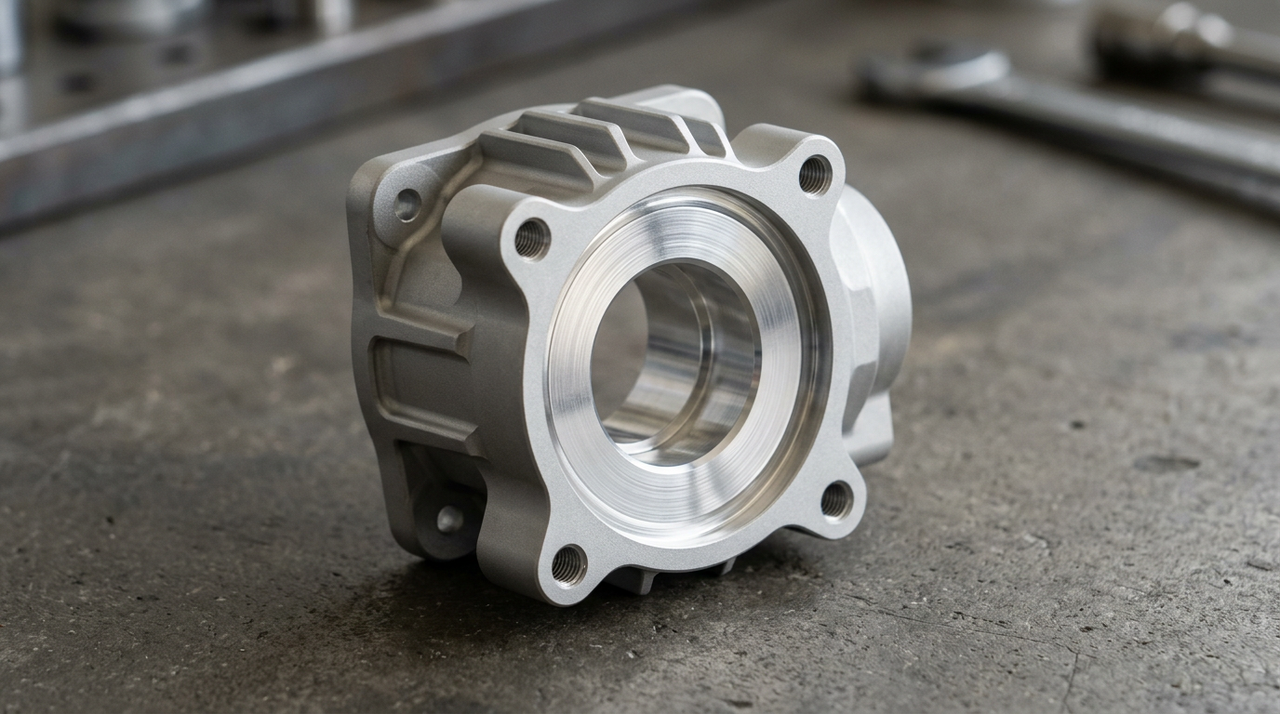
Bead blasting is a mechanical surface finishing process that propels small spherical media against a component, commonly using compressed air, to create a matte or satin texture.
Decide which surfaces can accept bead blasting before you approve the finishing route for a precision CNC part. A uniform matte enclosure often looks better after blasting, but the same treatment can ruin a bearing seat, sealing land, or close-fitting bore. For engineers and procurement teams ordering custom parts from Huaruida Precision Machinery, the useful question is not simply whether blasting is available; it is how the finish will be specified, isolated, and inspected on your drawing.
This guide explains how media and process settings influence surface quality, where dimensional risk arises, how to mask and sequence operations, and what to include in drawings and purchase requirements so prototypes and production parts meet both cosmetic and functional expectations without costly rework.
Start by separating appearance surfaces from functional interfaces. Bead blasting is often appropriate for visible housing walls, covers, handles, and exposed brackets where a diffuse, non-directional appearance is desirable. Precision bores, locating datums, threads, electrical contact areas, and sealing faces need individual review. A surface that looks cosmetic in the CAD model may still locate another component or establish an inspection reference, so it cannot be blasted on assumption.
Blasting is not dimensionally neutral. Repeated media impacts change surface topography and may cause localized material displacement, erosion, or edge rounding, depending on the substrate and process. Thin walls and delicate features can also distort under aggressive exposure. These effects may be inconsequential on a clearance surface but unacceptable where fit, flatness, or edge geometry is tightly controlled to a few microns.
Create a finish map on the drawing: blast these faces, protect these features, and inspect these characteristics after all relevant processing. For example, a robot sensor housing could receive a matte exterior while keeping its dowel holes and gasket groove unblasted. This feature-level approach is far more reliable than applying a general bead-blast note to every surface and expecting the supplier to infer the exceptions from experience.
Spherical glass beads are commonly selected for a satin or matte appearance, while ceramic beads offer another process option. Neither should be treated as interchangeable with angular cutting abrasives. Angular media generally have a more aggressive cutting action and can produce a more angular surface profile. Even with spherical media, the finish depends on bead size distribution, bead condition, substrate hardness, and the energy delivered to the surface.
Pressure alone does not define a repeatable recipe. Nozzle diameter, working distance, impact angle, traverse speed, exposure time, and overlapping passes all influence the result. Excessive dwell near an edge or pocket opening can create a visibly different band and increase local damage. Complex 5-axis parts need particular attention because recessed faces and external walls may not receive equivalent exposure during a single setup.
For repeat production, qualify a practical process window rather than a single nominal pressure. Record the media specification, equipment setup, part orientation, and acceptable exposure method. Control media breakdown and contamination as well: reused media changes the finish as it fractures and accumulates debris, so set a replacement or screening interval. An approved sample made from the same alloy and initial machined condition gives these process controls a meaningful visual reference.
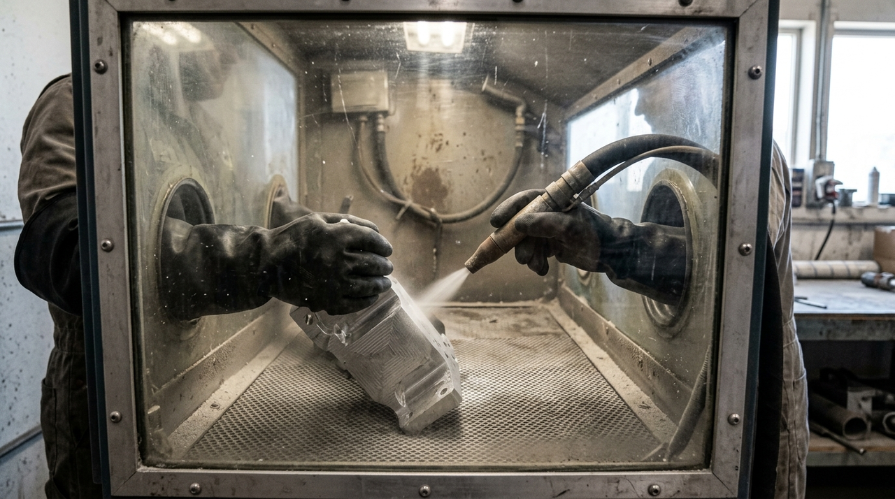
Bead blasting can soften the visual contrast of machining marks without removing the underlying feed pattern. Deep tool marks, chatter, scratches, and dents may remain visible after treatment. If the requirement is a consistent cosmetic surface, the machining stage must already deliver a suitable baseline. Increasing blast intensity to hide poor machining can damage edges or functional features without solving the original defect.
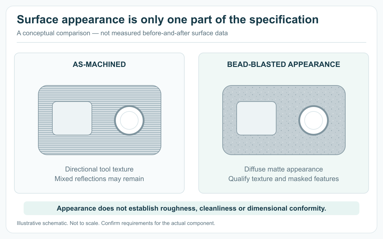
Conceptual surface comparison: a matte appearance does not by itself establish roughness or dimensional conformity.
Appearance and measured roughness should be specified separately. A matte surface can have a higher or lower Ra than its starting condition, depending on the original texture and blasting process. Ra also cannot describe every feature relevant to sealing, wear, or appearance. For a fuller explanation of measurement parameters and their limitations, review this guide to surface roughness for CNC machined parts.
Where roughness affects function, state the parameter, allowable value or range, measurement locations, and applicable measurement method. Specify measurement direction and filtering or cutoff conditions when they matter to acceptance. For cosmetic faces, use an approved finish sample and defined viewing conditions. Requiring both a visual match and a roughness measurement is reasonable, but they are separate checks, not substitutes for one another.
Selective blasting protects the surfaces that control assembly while treating the areas that drive appearance. Full-part blasting reduces masking operations, but it is suitable only when every exposed feature can tolerate the process. The decision should follow the tolerance and function review, not simply the lowest finishing quotation. A small masking cost can prevent expensive rework of an otherwise complete CNC component.
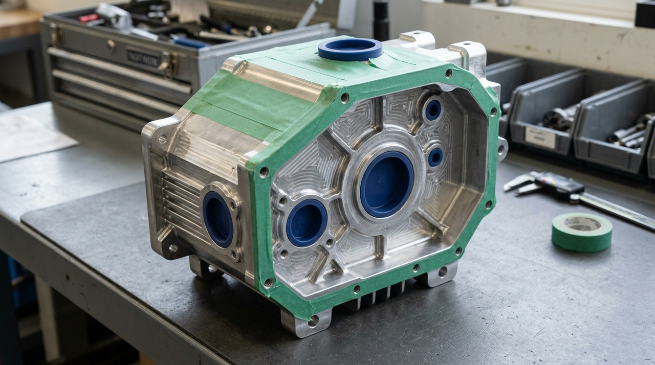
Use plugs, caps, fixtures, or blast-resistant masking materials matched to the feature and process. Masking must survive impact and prevent media from entering protected areas; ordinary tape or covering is not automatically adequate at working pressure. Specify the finish boundary where it affects appearance or assembly clearance. Around a bore opening, for example, identify whether the chamfer is blasted, protected, or allowed a defined transition zone.
Inspect masks before processing and verify protected features after removal. Poorly seated plugs can expose bore entrances, while adhesive residue can interfere with subsequent treatment. For recurring geometries, dedicated reusable fixtures may improve consistency and reduce handling time. Full-part blasting should still undergo first-article validation, especially when the design includes small threads, narrow slots, or sharp-edged locating features.
| Decision factor | Selective blasting | Full-part blasting |
|---|---|---|
| Tight fits and sealing faces | Protect designated interfaces and verify them afterward. | Use only if every exposed interface is validated for blasting. |
| Cosmetic coverage | Requires agreed boundaries and transition acceptance. | Avoids mask boundaries but may leave fixture contact areas. |
| Setup and handling | Adds masking work or dedicated fixture preparation. | Reduces masking, though positioning and cleaning remain necessary. |
| Internal passages | Can block entry when plugs seal effectively. | Requires reliable media removal from all exposed passages. |
| Repeat production | Reusable masks can stabilize protection and boundaries. | Controlled orientation and exposure remain essential. |
Qualify the finish on the actual alloy and material condition. Aluminum, stainless steel, brass, titanium, and engineering plastics respond differently to impact. Softer materials may show excessive texturing or embedded media more readily, while thin sections require conservative processing regardless of alloy. A finish sample from a different material is useful for discussing appearance, but it cannot establish the production recipe or dimensional effect.
For aluminum parts that will be anodized, blasting commonly precedes cleaning, pretreatment, and anodizing. Evaluate the finished anodized sample, not just the bare blasted surface: pretreatment, alloy variation, and the oxide layer can all alter appearance. Where coatings affect fit, account for coating buildup or substrate conversion in the dimensional plan. There is no universal machining allowance that covers both blasting and every subsequent treatment.
Control cross-contamination through suitable media management, equipment cleaning, or dedicated equipment where required. Stainless components, for example, should be protected from unwanted ferrous contamination that could cause corrosion. Medical and aerospace applications may impose additional cleanliness or surface-treatment requirements that must be stated explicitly. For brass components, compare the intended appearance and exposure conditions against surface finishing options for CNC brass parts before selecting the complete treatment sequence.
Use pre-blast measurements to establish a baseline on features most likely to change: precision diameters, thin-wall flatness, critical edges, and selected roughness locations. Repeat the relevant measurements after blasting during qualification. This comparison distinguishes machining variation from finishing effects and helps determine whether masking, reduced exposure, or a different sequence is necessary. For final acceptance, inspect at the stage specified by the drawing, normally after applicable finishing.
Do not assign a generic dimensional allowance for bead blasting. The effect depends on the material, geometry, media, and exposure, and may vary across the part. If qualification shows unacceptable change on an unmasked feature, first consider protecting it or moving its final machining operation after blasting. Post-blast machining can restore precision, but it introduces bright machined areas and requires careful handling to avoid damaging adjacent finished surfaces.
Choose inspection methods appropriate to the feature and surface texture. CMM probing, micrometers, bore gauges, thread gauges, and profilometry answer different questions; texture and edge rounding can also influence measurement interpretation. Use consistent locations and methods when comparing results. A first-article report should identify the part's finish condition and the characteristics checked, so an acceptable pre-finish measurement is not mistaken for evidence of final conformity.
A satisfactory blasted appearance does not establish that a part is clean. Beads and debris can remain in blind holes, intersecting passages, narrow grooves, and threads. Plan access for cleaning before approving the process, especially for components used near bearings, lubricated mechanisms, optics, or fluid paths. If trapped media cannot be removed and verified reliably, those areas should be isolated from blasting or processed differently.
Specify a cleaning method compatible with the material, geometry, and subsequent treatment. Air blow-off alone may be insufficient for difficult cavities or stringent cleanliness requirements. Depending on the application, a qualified sequence may include washing, rinsing, ultrasonic cleaning where suitable, and controlled drying. Any residue or particle acceptance limits should come from the product's actual service requirements, rather than an undefined request for a clean part.
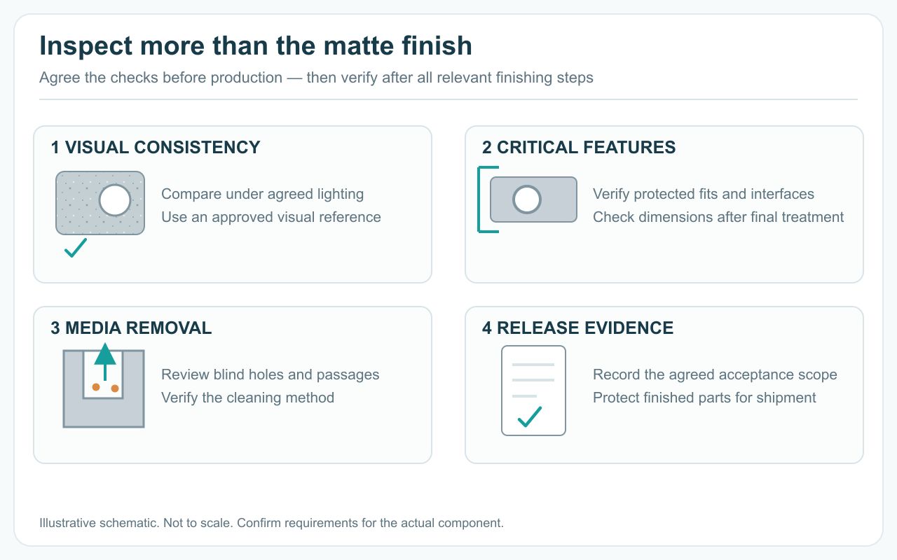
Post-blast inspection should cover appearance, critical features, trapped media and the agreed release evidence.
Inspect appearance under agreed lighting, viewing distance, and orientation. Check for uneven texture, residual tool marks, impact damage, mask leakage, and inconsistent boundaries. Separate significant visible faces from concealed surfaces so inspection effort follows product value. After acceptance, use nonabrasive separation and suitable packaging to prevent rubbing and fingerprints; an otherwise acceptable matte surface can acquire handling marks during transport or assembly.
Send the supplier a controlled drawing, CAD model, material specification, production quantity, and annotated finish map. Identify appearance-critical faces, prohibited blast areas, final dimensional tolerances, roughness requirements, and any subsequent coatings. If a visual reference is important, provide a physical sample or arrange sample approval. Photographs help explain intent but are unreliable as the sole reference because lighting can disguise texture differences.
Ask for quotation assumptions to separate machining, finishing, masking or fixtures, inspection, and any qualification work where relevant. On a single prototype, manual masking may be economical; repeated low-volume batches may justify reusable tooling. Also identify design details that increase finishing cost, such as numerous tiny protected holes or inaccessible cavities. Moving a cosmetic boundary or simplifying a protected region can reduce labor without compromising performance.
For a project discussion with Huaruida Precision Machinery, request confirmation of the proposed finishing sequence and final inspection scope before releasing the order. Agree how changes to media, equipment, masking, or process settings will be reviewed when they could affect acceptance. Approve a representative first article before broader production. This creates a shared baseline for appearance and fit instead of relying on the ambiguous instruction to make the parts bead blasted.
It can. Media impacts alter surface texture and may produce localized erosion, material displacement, or edge rounding. The effect depends on the material and process, so protect critical features and validate final dimensions rather than assuming zero change.
There is no universal Ra value. Starting roughness, alloy, media size and condition, pressure, and exposure all influence the result. Specify the required roughness and measurement method, then qualify the process on representative parts.
It can reduce their visual contrast, but deep feed marks and chatter may remain. Establish suitable surface quality during machining rather than relying on aggressive blasting to hide defects.
Precision threads, bearing seats, and close-fitting bores generally warrant protection unless testing demonstrates that blasting meets their functional requirements. Define whether adjacent chamfers and bore entrances also need masking.
No. Although both involve media impacts, controlled shot peening is specified to produce defined mechanical effects using requirements such as intensity and coverage. Cosmetic bead blasting should not be credited with equivalent fatigue benefits.
Yes, blasting is commonly performed before cleaning, pretreatment, and anodizing. Approve the appearance after the complete sequence, and specify whether critical dimensions apply after anodizing.
Products

45# Steel

45# Steel

45# Steel

Aluminum Tube

Aluminum Alloy

45# Steel

Aluminum Alloy

304 Stainless Steel
Navigation
Navigation
Contact Us
Tel: +86 13417419143
E-mail: [email protected]
Add:
2nd Floor, Building 7, 156 High Tech Industrial Park, Fuyuan 1st Road, Zhancheng Community, Fuhai Street, Baoan District, Shenzhen City, China.


