Sep.
05, 2026
Contents
When Standard Mounts Cannot Support the Robot's Load Case
Converting Robot Loads into a Machinable Mount Geometry
Choosing Aluminum, Steel, or Stainless Steel for Robot Mounts
Datums and Tolerances That Protect Drivetrain Alignment
CNC Strategies for Large, Rigid, Accurate Brackets
Threads, Inserts, Fasteners, and Service Access
From Prototype Validation to Repeatable Production
Inspection Evidence Procurement Teams Should Request
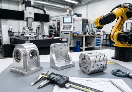
Selecting a motor is only part of designing a high-payload robot. The structure connecting that motor to the arm, gearbox, or machine frame must resist static payloads, acceleration forces, emergency-stop loads, and repeated changes in direction. If the mount deflects, slips, or loses alignment, even a correctly sized drive system can suffer from positioning errors, bearing wear, vibration, and shortened service life. This is why custom robot motor mounts often become critical structural components rather than simple supporting brackets.
A standard catalog mount may be adequate when its interface dimensions, stiffness, and environmental rating match the application. Custom machining becomes necessary when the robot uses a nonstandard motor-and-gearbox combination, operates within a restricted envelope, carries unusually high dynamic loads, or requires integrated cable routing, sensors, guards, or cooling features. It also allows engineers to replace multi-piece welded assemblies with a single machined component when improved alignment and repeatability justify the change.
The decision should begin with an engineering load case, not only a payload figure. A 200 kg payload held close to an axis produces a different bending moment from the same mass located at the end of a long arm. Designers should document the motor torque, gearbox reaction torque, center-of-mass offset, maximum acceleration, duty cycle, anticipated shock events, mounting orientation, operating temperature, and required service life before releasing the part for CNC machining. Safety factors and acceptance criteria should be established by the robot designer according to the actual application and relevant requirements.
A useful motor-mount model identifies how forces travel from the motor flange through the component and into the robot structure. Bolt circles, pilot diameters, locating shoulders, mounting feet, ribs, and wall transitions all influence that load path. Thin walls or abrupt section changes near highly loaded interfaces can create localized stress and deflection. Finite element analysis can help compare design concepts, but its results depend on realistic constraints, contact assumptions, material properties, and load inputs.
The motor pilot or register should normally control concentric location, while the fasteners provide clamping force. Relying on loose-clearance bolts to locate the motor can allow radial movement during torque reversals. When repeatable removal and reinstallation matter, dowel holes, fitted shoulders, or precision locating surfaces may be appropriate. These features should be positioned so that they can be machined and inspected relative to the functional datums without unnecessary setups.
Manufacturability should be reviewed before the design is frozen. Deep narrow pockets, inaccessible internal corners, very thin ribs, and extreme reach-to-diameter ratios can increase tool deflection and cycle time. Internal corners require radii because rotating cutters cannot produce perfectly sharp corners. Increasing a corner radius, opening tool access, or using a through-pocket instead of a blind cavity can significantly improve machining stability without compromising function. A machining supplier of precision CNC machined parts can also identify where 5-axis access could consolidate setups or where a simpler three-axis design would be more economical.
Material selection should balance stiffness, strength, mass, machinability, corrosion exposure, and thermal behavior. Aluminum alloys are frequently considered for moving robot axes because their low density reduces inertial load. They are readily machinable and can accept protective surface treatments. However, aluminum has a lower elastic modulus than steel, so an aluminum mount may need thicker sections or deeper ribs to achieve comparable stiffness. Thread engagement, bearing pressure around fasteners, and local deformation under clamping also deserve attention.
Carbon and alloy steels provide higher stiffness and can support compact, highly loaded geometries. They may suit stationary bases, heavy joint housings, or mounts where added mass has little effect on robot dynamics. The tradeoffs can include longer machining times, greater tool wear, corrosion protection requirements, and distortion from heat treatment. If a steel component will be hardened, the drawing should define whether critical dimensions are to be finished before or after heat treatment.
Stainless steel can be useful in wet, corrosive, food-processing, pharmaceutical, or clean equipment environments, subject to the application's material and sanitation requirements. It is generally more demanding to machine than common aluminum alloys and can retain heat at the cutting edge. No material should be selected from tensile strength alone. Engineers should compare elastic deflection, fatigue behavior, surface pressure, galvanic compatibility, temperature range, coating needs, and total moving mass before approving the final specification.
Applying tight tolerances to every dimension increases manufacturing cost without necessarily improving robot performance. The drawing should distinguish functional interfaces from clearance surfaces. Critical characteristics commonly include the motor-register diameter, flange flatness, perpendicularity between the motor face and gearbox axis, true position of locating holes, and parallelism between mounting planes. Cosmetic pockets, outer profiles, and non-contact surfaces can often use broader tolerances.
A coherent datum structure makes those requirements measurable. For example, the primary datum may be the robot-frame mounting plane, the secondary datum a locating edge or bore, and the tertiary datum another feature that fixes rotation. Motor bores and fastener patterns can then be controlled relative to the same functional reference system. This approach is more useful than attaching isolated plus-or-minus tolerances to coordinates that do not represent assembly behavior.
Tolerance stack-up should include the motor flange, mount, gearbox adapter, couplings, bearings, and mating robot structure. If every component consumes its full allowable error in the same direction, the resulting shaft misalignment may exceed the coupling's capability. Designers should therefore allocate tolerances at assembly level and tighten only the contributors that materially affect alignment. Requirements for surface finish should also be selective: sealing faces, bearing seats, and precision pilots may need controlled finishes, while a finer finish on unloaded surfaces usually adds avoidable machining time.
The manufacturing plan must preserve relationships between functional features while controlling residual stress and part movement. A typical approach is to rough-machine the component with stock left on critical surfaces, allow stresses to redistribute, and then finish the locating bores and mounting planes. For large aluminum billets or stress-sensitive geometries, balanced stock removal from opposing sides can reduce the risk of warping. Steel parts may require additional consideration if welding, heat treatment, or aggressive roughing precedes finish machining.
Multiple setups can introduce error whenever the component is removed and relocated. five-axis machining can improve access to angled faces, intersecting holes, and complex pockets while reducing repositioning. It can also keep shorter cutting tools in contact with deep features, improving rigidity. However, five-axis equipment is not automatically the best choice for every mount. A prismatic bracket with features on two or three orthogonal faces may be produced efficiently with conventional CNC milling and well-designed fixtures.
Workholding is especially important for thin-wall mounts and large ring-shaped adapters. Excessive clamping force can distort the component during cutting; when released, the finished feature may move out of tolerance. Machinists may use sacrificial tabs, soft jaws, expanding fixtures, or purpose-built supports to distribute force. The sequence should leave enough material to resist vibration until the major roughing operations are complete, with final cuts taken under stable and repeatable conditions.
Threaded connections must carry preload reliably throughout repeated robot motion. The correct thread size and engagement depend on the base material, fastener strength, load direction, tightening method, and frequency of service. Aluminum threads may need greater engagement than steel threads. Thread inserts can improve wear resistance when motors are changed frequently, but they should be specified intentionally because insertion, inspection, and replacement affect the production and maintenance plan.
Fastener layout should allow tools to reach each screw without removing unrelated robot components. Counterbores require sufficient wall thickness beneath the head, while spotfaces should provide consistent seating on cast, sloped, or sculpted surfaces. Designers should also verify that bolts do not bottom in blind holes and that drill points cannot break into adjacent cable channels or precision bores. Clear assembly drawings help prevent confusion between mounting holes, jacking-screw holes, and extraction features.
Pins and shoulders should locate components without making maintenance unnecessarily difficult. If a closely fitted pilot may seize because of corrosion, contamination, or temperature changes, extraction holes or suitable clearances can support servicing. Cable routing is another practical concern: machined passages should avoid sharp edges and maintain adequate clearance from rotating couplings and hot motor surfaces. Any lifting points added to a heavy mount should be engineered for the intended handling procedure rather than treated as ordinary threaded holes.
A prototype should test more than whether the mount physically fits. Assembly trials can verify motor installation, connector access, bolt-tool clearance, cable bend radius, guard clearance, and the ability to remove the drive without dismantling an entire axis. Dimensional inspection should then be linked to functional tests such as shaft alignment, no-load motion, vibration, thermal growth, and positional repeatability. Testing under representative payload and acceleration conditions is more informative than checking the assembly only at rest.
Low-volume production provides an opportunity to stabilize the machining process before larger orders. The manufacturer can refine fixtures, cutting parameters, deburring methods, and inspection routines while the engineering team monitors field or endurance results. If design changes remain likely, configuration control is essential. Every purchase order and inspection report should identify the correct drawing revision, material condition, surface treatment, and approved deviations.
For repeat orders, buyers should provide a complete technical package rather than relying on a 3D model alone. A useful package includes a STEP file or another suitable neutral model, a dimensioned drawing, datum and geometric tolerance definitions, material specifications, treatment requirements, thread details, quantity, revision level, and inspection expectations. Supplying annual demand estimates and likely batch sizes can also help the manufacturer propose suitable tooling and production methods without assuming that prototype economics will apply to volume production.
Inspection should focus on characteristics that control assembly and performance. Depending on the design, a coordinate measuring machine may be used to verify hole patterns, bore positions, perpendicularity, and profile relationships. Height gauges, micrometers, bore gauges, surface plates, thread gauges, and surface roughness instruments may be more efficient for other features. The selected method must be capable of resolving the tolerance and should reflect how the feature functions in the robot.
A first-article report can document critical dimensions before a production batch proceeds, while in-process checks help identify tool wear or fixture movement. Procurement teams should agree in advance on the required reporting scope, sampling plan, measurement units, drawing revision, and treatment documentation. If a mating motor, gearbox, or master gauge is available, a controlled fit check may supplement dimensional measurements, although it should not replace appropriate inspection of defined characteristics.
Huaruida Precision Machinery supports custom CNC machining from prototype development through production quantities, including CNC milling, turning, 5-axis machining, surface treatments, and complementary fabrication processes. For an effective quotation, customers should identify the mount's critical interfaces, expected quantity, target application, and inspection needs. Early design-for-manufacturing communication can reduce avoidable complexity while preserving the stiffness, alignment, and serviceability required by a high-payload industrial robot.
Provide a 3D CAD model, dimensioned drawing, material and treatment specifications, quantity, drawing revision, critical tolerances, thread details, and inspection requirements. Application and load information can also support a useful manufacturability review.
It can be, but suitability depends on geometry, stiffness, torque, fatigue loading, fastener pressure, and safety factors. Aluminum often requires thicker walls or deeper ribs than steel to achieve the required rigidity.
It is useful for mounts with angled interfaces, features on several faces, deep pockets, or complex contours. Reducing setups can improve positional relationships, although simpler parts may be more economical on three-axis equipment.
Motor pilots, gearbox bores, locating holes, shaft-related features, flange flatness, and perpendicularity between mating faces are often critical. Exact requirements should come from an assembly-level tolerance analysis.
They may be beneficial for frequently serviced connections or threads exposed to high wear. The decision should consider load, engagement length, maintenance frequency, available wall thickness, and installation control.
Combine dimensional inspection with assembly, alignment, vibration, thermal, access, and representative load testing. Results should be recorded against the correct drawing revision before the process is released for repeat production.
Latest News


Products

45# Steel

45# Steel

45# Steel

Aluminum Tube

Aluminum Alloy

45# Steel

Aluminum Alloy

304 Stainless Steel
Navigation
Navigation
Contact Us
Tel: +86 13417419143
E-mail: [email protected]
Add:
2nd Floor, Building 7, 156 High Tech Industrial Park, Fuyuan 1st Road, Zhancheng Community, Fuhai Street, Baoan District, Shenzhen City, China.
