Oct.
21, 2026
Contents
When Rotational Geometry Makes Lathe Machining the Better Choice
How the Operation Sequence Protects Precision
Design Features That Tools Can Reach and Support
Which Turning Tolerances Actually Control Assembly Performance?
Material Selection Changes More Than Cutting Speed
Surface Finish, Coatings, and Edge Conditions
Build the Inspection Plan Around Critical Features
What to Include in a Quote-Ready Turning Package
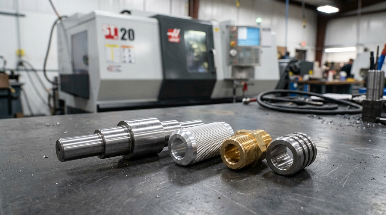
Deciding whether to turn a part, mill it, or combine both processes starts with its functional geometry—not simply whether it looks round. For shafts, bushings, threaded connectors, and actuator components, that choice affects concentricity, material use, inspection effort, and production cost. A design that works as a single prototype may still need changes before repeat orders become economical.
This guide explains how to choose a turning route, design accessible features, specify meaningful tolerances, select material, define surface finish, and prepare a quotation package that reduces manufacturing ambiguity. For engineers and buyers working with Huaruida Precision Machinery on custom precision parts, these steps create a clearer basis for discussing feasibility, quality requirements, and realistic delivery expectations before committing to tooling.
Lathe machining is usually a strong starting point when the critical geometry shares a common rotational axis. The workpiece rotates while cutting tools generate diameters, shoulders, tapers, grooves, and threads. Bearing sleeves and stepped shafts are typical candidates because several related surfaces can be produced without repeatedly relocating the part. This can simplify control of alignment between features, although machine condition, workholding rigidity, and inspection method still determine the final result.
Milling becomes more important when a component contains broad flat surfaces, pockets, or features distributed across several faces. A mostly cylindrical housing with wrench flats and a cross-hole may need turning followed by milling, or a suitable turning center with live tooling. Integrated machining can reduce transfers, but its value depends on equipment capability, feature accessibility, and batch size—not merely the number of operations counted on paper.
Identify which features establish the part's function before choosing a route. If a bearing diameter and seal seat must run accurately together, prioritize their relationship in the setup plan. If a mounting pocket controls assembly position, a milling operation may establish the more important reference. The comparison below helps frame that discussion with your supplier.
Decision factor | CNC turning | CNC milling |
|---|---|---|
Primary geometry | Efficient for cylindrical and axisymmetric features | Suited to prismatic shapes, pockets, and complex faces |
Feature relationships | Produces related diameters about one spindle axis | Establishes relationships between faces and hole patterns |
Typical starting stock | Round bar, tube, or a near-net blank | Plate, block, or a near-net blank |
Off-axis features | May require live tooling or a secondary operation | Generally accessible with suitable fixturing and tool orientation |
Workholding concern | Grip length, jaw pressure, and unsupported projection | Clamping access, locating surfaces, and cutter clearance |
A typical turning sequence begins with preparing stock and establishing a reference face. Rough turning removes most of the excess material, while finish turning brings selected surfaces to their final size and finish. Drilling creates an initial axial hole; boring can then improve its diameter, alignment, and form. Reaming may be appropriate for certain holes, but it generally follows the existing hole rather than correcting substantial location error introduced earlier in the cycle.
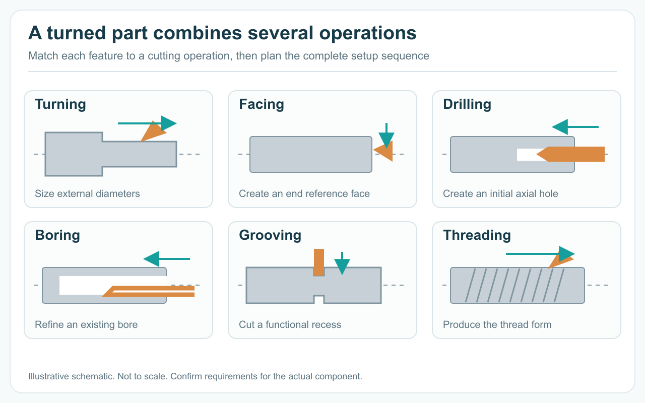
Feature-based turning sketches. Tool access, support, chip control and the actual operation sequence still require review.
Grooving, threading, and parting introduce different cutting loads and access requirements. External and internal threads need suitable entry and runout space, while narrow grooves require tools that can clear chips without rubbing. Parting separates a component from bar stock, but the cutoff end may need a second setup for facing, chamfering, or removal of a residual nub. Final length and end-face requirements should account for that additional step rather than assume a clean cut.
The sequence should also consider heat treatment and distortion. Hardened components may be rough-machined, heat-treated, and then finished by an appropriate process such as hard turning or grinding. For sensitive geometries, removing large amounts of stock can release residual stress and shift dimensions. Ask the supplier where finishing allowances, intermediate checks, and any stress-relief steps belong rather than assuming every surface can be completed in one uninterrupted cycle.
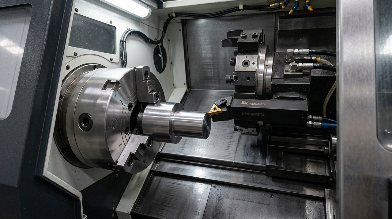
Long, slender sections can deflect under cutting forces, creating taper, chatter, or inconsistent size. A tailstock, steady rest, or different workholding strategy may help, but each requires access and suitable supporting geometry. Avoid treating any single length-to-diameter guideline as universal: material stiffness, cutting load, finished diameter, and support conditions all matter. Flag slender shafts early so the manufacturer can assess the setup before dimensions are frozen on the drawing.
Thin walls create a related problem. Chucking pressure can distort a sleeve during machining, so a bore that measures correctly while clamped may change after release. Where function permits, increase wall thickness, reduce unsupported projection, or provide a temporary gripping extension. Soft jaws, collets, and expanding mandrels can be useful options, but the choice must match the surfaces being finished and the acceptable clamping deformation for your tolerance.
At shoulders and internal corners, allow realistic tool geometry. A perfectly sharp internal corner is usually incompatible with the cutting insert's nose radius; a relief groove may provide clearance when a mating component must seat fully against the shoulder. Deep, small-diameter bores and narrow internal grooves require slender tools with limited rigidity. Specify only the depth needed for function, and provide thread reliefs or tool runout where assembly space allows.
Begin with the assembly requirement: clearance, interference, sealing, alignment, or rotational accuracy. A diameter tolerance controls size, but it does not by itself establish roundness, straightness, or alignment to another feature. A shaft can meet its diameter limits and still perform poorly if its bearing seats do not share the required axis. Use geometric controls where they express a real functional requirement rather than tightening every dimension indiscriminately.
Choose datums that represent how the component is located in service. For a rotating shaft, a bearing seat may establish the datum axis, while a shoulder establishes axial position. Runout, perpendicularity, or position controls can then communicate the necessary relationships. State the drawing standard used, and have the supplier review whether the proposed datum features are accessible for both manufacturing and inspection.
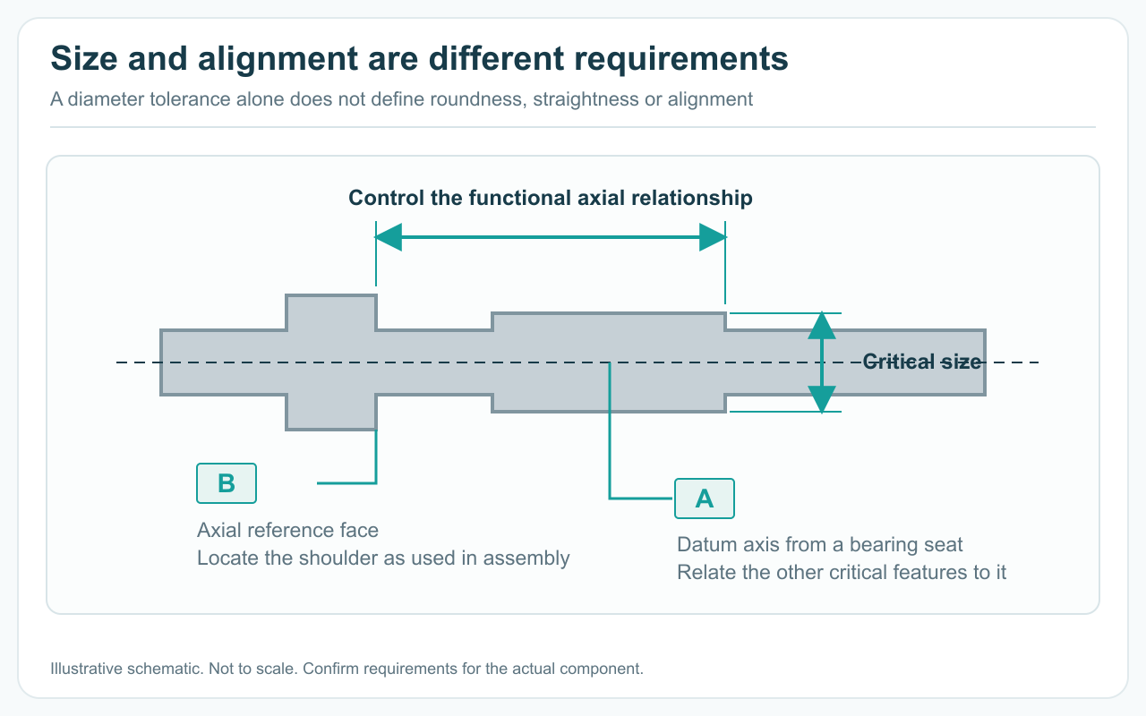
Example datum concept for a shaft. Select the actual datum scheme and geometric controls from assembly function and the drawing standard.
Treat tolerance capability as feature-specific. Material, wall thickness, unsupported length, tool access, and finishing operations all affect what is practical. For example, a short external journal and a deep internal bore should not automatically receive the same tolerance. Separate critical dimensions from general tolerances, identify whether requirements apply before or after finishing, and avoid conflicting tolerances between the drawing and the CAD model. This gives the supplier a defensible basis for costing and process planning.
Select the material grade and condition from service needs first, then evaluate machinability. Many aluminum alloys suit lightweight housings and automation components, but alloy and temper influence chip formation, strength, and finishing behavior. Stainless steels may provide the required corrosion resistance, yet some grades work-harden and demand careful control of cutting conditions. Neither category should be specified only as 'aluminum' or 'stainless steel' on a production drawing.
Brass is often useful for turned connectors and fittings, but its exact composition matters where restrictions on lead or other substances apply. Titanium can suit demanding strength-to-weight and corrosion requirements, although heat management and tooling deserve particular attention. Engineering plastics avoid some metal-related issues but introduce thermal expansion, moisture absorption, and deformation concerns. For regulated applications, review the intended use and material documentation requirements separately from machining feasibility.
Starting stock also affects cost and stability. Tube can reduce material removal for a hollow part, provided its available dimensions, wall allowance, and material condition meet the design needs. Round bar may offer a simpler route for small runs, while near-net blanks can become worth evaluating at higher volumes. Discuss acceptable material substitutions before quotation; changing grade after process planning can alter tooling, surface treatment compatibility, and inspection assumptions.
Assign surface finish requirements by function rather than appearance alone. A seal contact surface, sliding bore, and cosmetic outside diameter may each need different treatment. Specify a roughness parameter and limit where necessary, but recognize that a single value such as Ra does not fully describe texture direction, waviness, or isolated defects. On dynamic sealing surfaces, the lay pattern left by turning may matter as much as the average roughness number.
If grinding, honing, polishing, or another finishing operation is needed, account for it in the process route and machining allowance. Anodizing and plating can change dimensions and therefore affect fits, threads, and small holes. State which dimensions apply after treatment and identify any masked areas. Coating growth and distribution depend on the process, so obtain supplier input instead of applying one assumed allowance to every surface.
Edge requirements deserve explicit notes. A generic instruction to deburr does not define the permitted edge break at a sharp functional shoulder or small sealing feature. Cross-holes intersecting bores can leave difficult-to-access burrs, while polishing can unintentionally round precision edges. Mark sensitive areas and define cleanliness expectations where chips or residue would affect assembly. For application-specific considerations, review this guide to precision machining for medical device parts, while keeping component inspection distinct from device-level validation.
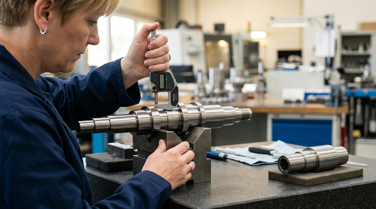
Inspection should follow the drawing's functional priorities. External diameters may be checked with suitable micrometers, while internal features may require bore gauges, plug gauges, or other methods appropriate to their size and tolerance. Threads need checks matched to the specified thread system and acceptance requirements. Coordinate measurement can help assess feature relationships, but it is not automatically the best method for every small bore, surface texture, or form requirement.
Agree on measurement conditions for sensitive features. Thin-walled parts may need verification in an unclamped state; plastics and close-tolerance metal parts can require attention to temperature stabilization. The measurement method must have sufficient resolution and acceptable uncertainty for the tolerance being evaluated. Where a datum setup is complex, request clarification of the inspection alignment so supplier and customer do not obtain conflicting results from different interpretations.
Huaruida Precision Machinery emphasizes 100% inspection before packaging, but buyers should still define the scope of that inspection for their project. Inspection of every part does not necessarily mean recording every characteristic on every part. Identify dimensions requiring documented results, any first-article expectations, material records, and lot traceability needs. Protective packaging should also reflect the geometry: precision threads, polished journals, and thin edges may need separation or individual protection during international transport.
Submit a revision-controlled 3D model and a dimensioned drawing that identifies material grade, condition, tolerances, datums, thread details, surface finish, and treatment requirements. State which document governs if information conflicts. Include prototype quantity, expected repeat quantities, and any assembly constraints that are not obvious from the geometry. A supplier can evaluate alternatives more effectively when it knows which features are negotiable and which protect essential performance.
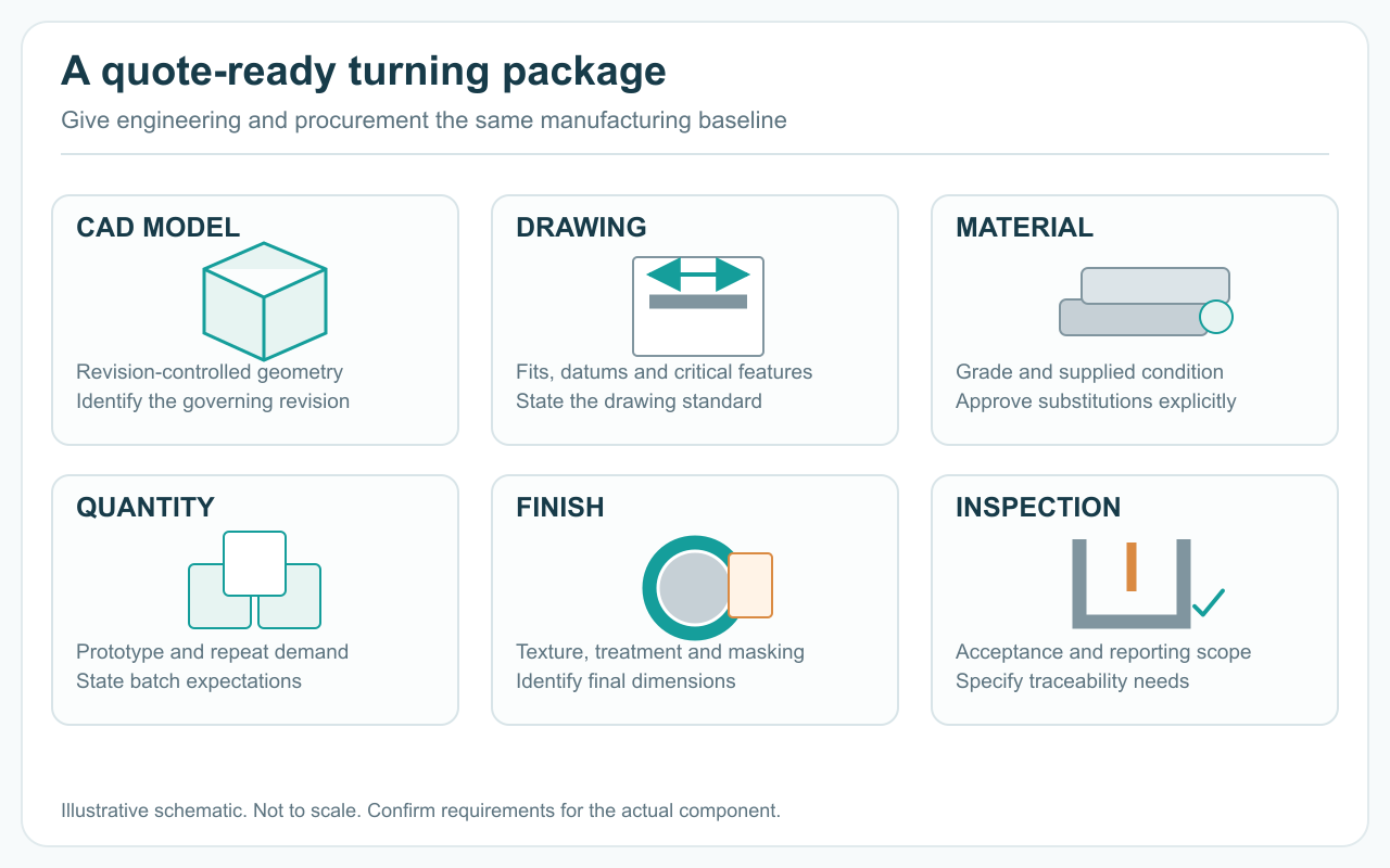
Send the model and controlled drawing together with material, quantity, finish and inspection requirements.
Ask for the assumptions behind the quotation, not just the total. Useful questions cover setup count, secondary milling, special tooling, inspection reporting, outside finishing, and packaging. Request that proposed design changes be separated from the quoted baseline so you can compare options fairly. For supplier evaluation beyond one component, the guide to choosing a precision machining parts manufacturer can help structure the purchasing discussion.
Use the prototype stage to resolve manufacturing risks before scaling. Check fit with mating components, review burr-prone intersections, and confirm that finishing has not altered critical dimensions. For repeat orders, retain an approved drawing revision and documented acceptance criteria rather than relying solely on a physical sample. Huaruida's combination of CNC turning, milling, surface treatments, and prototype-to-production services provides a relevant starting point for discussing the complete route, with project-specific capability and timing confirmed during technical review.
Lathe machining describes material removal with a rotating workpiece, whether the machine is manually operated or computer-controlled. CNC turning uses programmed machine movements to produce those features with repeatable toolpaths and controlled operating parameters.
Yes. These features can be made in secondary milling or drilling operations, or on a suitably equipped turning center with live tooling. Tool access, feature orientation, workholding, and available equipment determine the best route.
Use the tolerance needed for the fit or function, then confirm feasibility with the supplier. Achievable results depend on material, geometry, support, thermal behavior, and finishing. Apply tighter limits selectively rather than to every diameter.
Grinding may be appropriate when hardness, dimensional control, form, or surface requirements exceed what the planned turning process can reliably deliver. It is not mandatory for every precision part; evaluate it against the specific drawing requirements.
Reduce unnecessary setups, allow practical corner radii and tool access, avoid deeper bores than needed, and limit tight tolerances to functional features. Discuss suitable stock sizes and inspection scope before changing material or compromising performance.
Products

45# Steel

45# Steel

45# Steel

Aluminum Tube

Aluminum Alloy

45# Steel

Aluminum Alloy

304 Stainless Steel
Navigation
Navigation
Contact Us
Tel: +86 13417419143
E-mail: [email protected]
Add:
2nd Floor, Building 7, 156 High Tech Industrial Park, Fuyuan 1st Road, Zhancheng Community, Fuhai Street, Baoan District, Shenzhen City, China.


